120° mode inverter – circuit diagram, operation and formula 3-phase pwm power inverter circuit Pengaturan kecepatan motor induksi dengan inverter vfd atau vsd
SiC/IGBT 3 Phase Inverter Development Kit | Taraz Technologies
Inverter phase circuit schematic igbt
Inverter igbt
Inverter phase igbt electronics12+ 3 phase igbt inverter circuit diagram 12+ 3 phase igbt inverter circuit diagramPower circuit diagram of an igbt based single phase full-bridge.
Sic/igbt 3 phase inverter development kitThree phase inverter : circuit, working and its applications Inverter phase circuit pwm bridge full power diagram three schematic switching voltage controlledIgbt circuit module schematic fig4.
![Three Phase Inverter Schematic | Download Scientific Diagram](https://i2.wp.com/www.researchgate.net/profile/Luca_Sani/publication/269255065/figure/download/fig6/AS:300043929178116@1448547455253/Three-Phase-Inverter-Schematic.png)
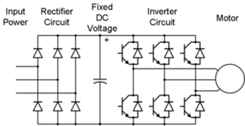
Inverter igbt power diagrams diode supply
12+ 3 phase igbt inverter circuit diagramIgbt inverter pwm switching frequency Three phase inverter schematicInverter circuit diagram 120 mode operation phase three bridge power formula figure shown below electrical.
Circuit schematic of igbt module .
![12+ 3 Phase Igbt Inverter Circuit Diagram | Robhosking Diagram](https://i2.wp.com/ai2-s2-public.s3.amazonaws.com/figures/2017-08-08/925e1b3d2c8359e95ce6dda69b353fcf538ccd6a/3-Figure4-1.png)
![3-Phase PWM Power Inverter Circuit](https://i2.wp.com/www.powerinverter.org/image/voltage-type-three-phase-full-bridge-inverter-structure-4501.jpg)
![120° Mode Inverter – Circuit Diagram, Operation and Formula](https://i2.wp.com/electricalbaba.com/wp-content/uploads/2020/09/circuit-diagram-of-three-phase-bridge-inverter.jpg)
![Pengaturan Kecepatan Motor Induksi Dengan Inverter VFD atau VSD](https://1.bp.blogspot.com/-EtkkPTITC7M/WnRQ25INb1I/AAAAAAAAGpM/-11bFIgspOwyhe56H7Affvj1LfmmSPE0wCLcBGAs/s1600/skema%2Binverter.jpg)
![SiC/IGBT 3 Phase Inverter Development Kit | Taraz Technologies](https://i2.wp.com/www.taraztechnologies.com/wp-content/uploads/2020/02/SPM-VFD-v2.png)
![12+ 3 Phase Igbt Inverter Circuit Diagram | Robhosking Diagram](https://i2.wp.com/www.electronics-tutorial.net/wp-content/uploads/2015/09/inverter24.png)
![12+ 3 Phase Igbt Inverter Circuit Diagram | Robhosking Diagram](https://i2.wp.com/img.alicdn.com/imgextra/i3/6000000000783/TB2W6QeCMaTBuNjSszfXXXgfpXa_!!6000000000783-0-tbvideo.jpg)
![Circuit schematic of IGBT module | Download Scientific Diagram](https://i2.wp.com/www.researchgate.net/profile/Xiaobing_Luo4/publication/261076220/figure/fig4/AS:392447415865349@1470578163679/Circuit-schematic-of-IGBT-module.png)
![Three Phase Inverter : Circuit, Working and Its Applications](https://i2.wp.com/www.elprocus.com/wp-content/uploads/Three-Phase-Inverter-Circuit.png)
![Power circuit diagram of an IGBT based single phase full-bridge](https://i2.wp.com/www.researchgate.net/profile/Hassan-M-Abdar/publication/261459665/figure/fig1/AS:296938747514883@1447807122790/Power-circuit-diagram-of-an-IGBT-based-single-phase-full-bridge-inverter.png)